Hydrocyclones and Separators™ are simple devices used for various applications in the production of sand products. They can be used for sizing, dewatering, desliming, fines recovery and primary sand production, with Separators™ additionally being used for stockpiling, providing consistent feed to Attrition Cells/Scrubbers and thickening feed to Dewatering Screens.
How Hydrocyclones and Separators™ function
When troubleshooting Hydrocyclones and Separators™, it is first important to understand how these devices function.
Slurry enters the feed inlet at a designated pressure and volume and follows the fall of the upper cylinder in a rotating action. Centrifugal forces send coarser material to the outer wall to travel downward and be further accelerated in the conical section. The coarser fractions exit through the apex or spigot at the bottom of the unit, while the finer fractions remain rotating in the inner core and are sucked upward by an air core.
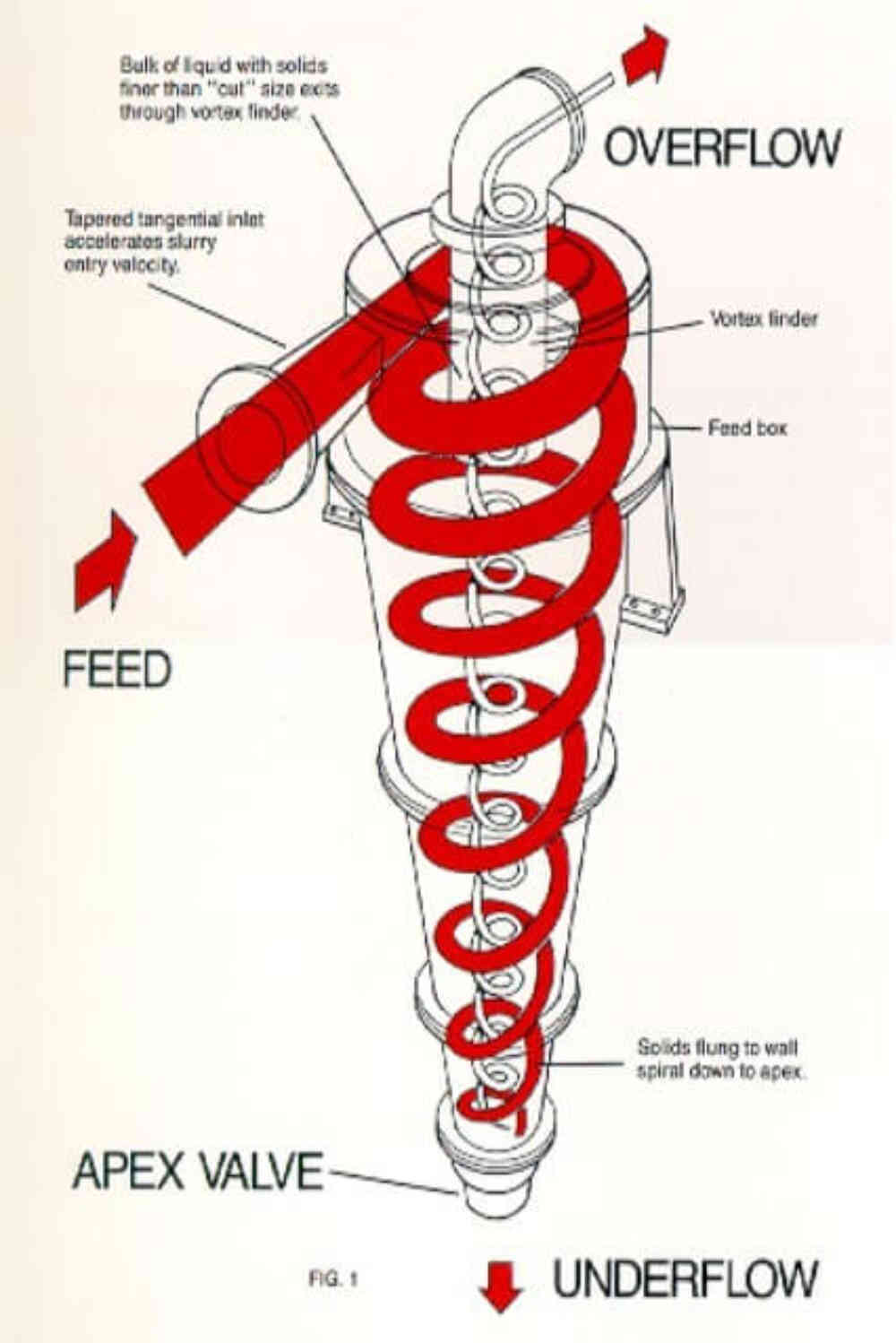
The air core is important for the proper operation of the Hydrocyclone. It is formed at the spigot as air is drawn into the Hydrocyclone. The vortex finder provides a pathway for the air to exit the body of the unit. As the air flows through the vortex finder, the fluids and finer fractions are dragged along to perform the classification of materials.
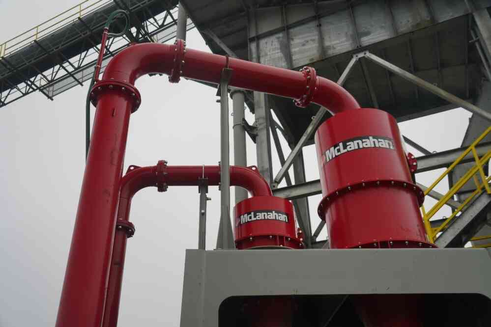
Separators™ are a siphon-assisted variant of a Hydrocyclone that feature the addition of an underflow regulator, extended overflow pipe, siphon control regulator and siphon boot.
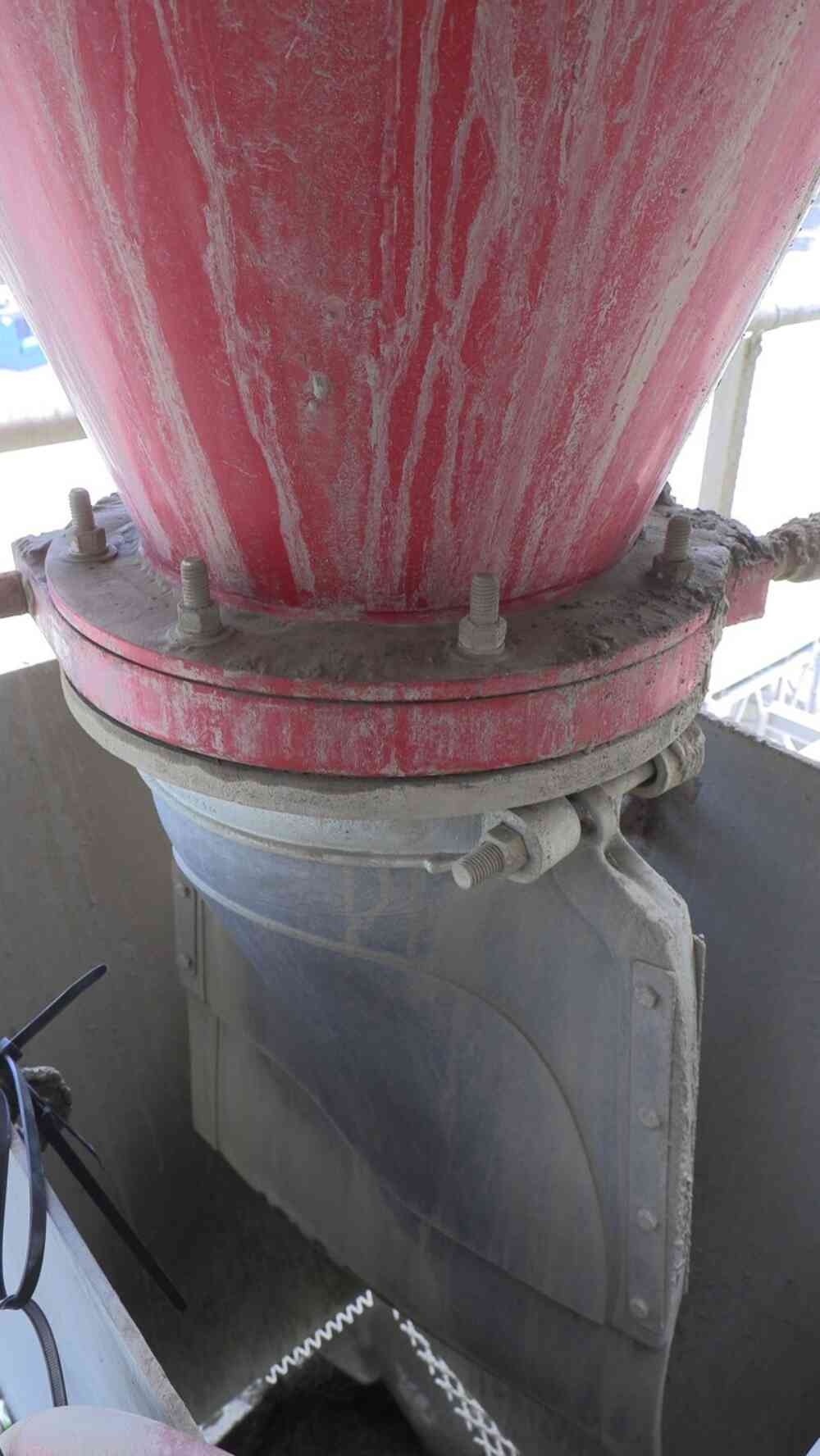
When the Separator™ is in operation, the extended overflow pipe fills with water and functions as a siphon, creating a negative pressure within the Separator™. This force draws the rubber underflow regulator closed. When sufficient solids have reported to the lower discharge spigot; the regulator is opened by the pressure of the solids and discharges.
This siphon feature allows Separators™ to discharge a more dewatered underflow than Hydrocyclones to allow for stockpiling or feeding other process equipment.
Performance
Because Hydrocyclones and Separators™ contain no moving parts, troubleshooting issues with these devices may seem difficult, especially since all the separation takes place out of sight. However, the symptoms presented by the Hydrocyclone or Separator™ can give clues to the root of the problem.
The performance of Hydrocyclones and Separators™ is influenced by the size of the unit, operating pressure, inlet area, vortex finder diameter, underflow and overflow diameters, cylindrical sections and cone angle. If the performance of the Hydrocyclone or Separator™ is not where it needs to be, there are three areas you can look at to help determine the potential cause:
- Feed
- Underflow
- Overflow
Note: when troubleshooting equipment and making any subsequent repairs, be sure to wear appropriate personal protective equipment and follow all safety regulations and requirements.
Feed
Hydrocyclones and Separators™ depend on another piece of equipment to provide a steady flow rate and drive performance. Most commonly, a sump and Slurry Pump fill this role.

The separation point for both Hydrocyclones and Separators™ is tied directly to their inlet pressure. When the pressure is not where it needs to be, the separation efficiency (or performance) of these devices is negatively impacted. Knowing what the inlet pressure should be and what it actually is will allow you to start the process of troubleshooting either of these units.
For example, Separators™ have an operating range of 5.5-14.5 psi. When the pressure falls below or exceeds these limits, a Separator™ no longer performs in a predictive manner. When the pressure is too high, more fines report to the underflow. When the pressure is too low, more fines report to the overflow. If the pressure falls below the recommended operational limit, the siphon won’t be able to form. A pressure gauge on the inlet can indicate this problem faster than any other method.
Fluctuation in the inlet pressure can indicate a problem with the Pump or sump (or alternate source) or can indicate air in the line. These issues must be addressed at the source of the feed since Hydrocyclones and Separators™ completely depend on a steady flow rate of air-free slurry to operate properly.
Too many or too little solids in the feed slurry can cause performance issues for Hydrocyclones and to a lesser extent with Separators™. With Hydrocyclones, the internal diameter of the apex determines the amount of water in the underflow. Fines bypass increases with an increase in water in the underflow, so material that is supposed to go to the overflow ends up misreporting to the underflow. On the opposite end, too many solids will overload the apex and collapse the air core required for the separation process to take place.
A Separator™ is more forgiving when it come to the amount of solids in the feed. Too little solids can affect the underflow density, but the larger issue is too many solids in the feed. When a Separator™ operates above 25% solids by weight, it runs the risk of not forming a siphon. The greater the number of solids in the feed above 25%, the higher the risk of the siphon not forming correctly or at all.
Challenge: pressure gauge reading fluctuating severely - surging
If the pressure is severely fluctuating or surging, it could be that the feed Pump is running with insufficient feed. Add more make-up water at the sump.
Underflow
Monitoring the underflow is essential when operating a Hydrocyclone or Separator™. It can provide significant clues to what is going wrong even when it is not the source of the problem.
A blocked spigot will send material to the overflow in both types of units. Potential blockages come from all different directions and include the liners of the unit, a foreign object introduced upstream or oversized material.
A partial block of a Hydrocyclone will look similar to when a person puts their finger over a hose and partially blocks the flow of water out of it. A normal Hydrocyclone spigot discharge will look like a cone of water sprayed out.
A blocked spigot could also be the result of a collapsed liner. A collapsed liner will disrupt the internal circular motion within the Hydrocylone or Separator™ and cause a blockage at the spigot area.
A blockage will be less obvious with a Separator™ because of the dewatered nature of the discharge. There is a chance the siphon of the overflow pipe could pull the blockage out; the siphon can be strong enough to pull the liners completely out if they are not secure enough.
Challenge: spigot not discharging correctly
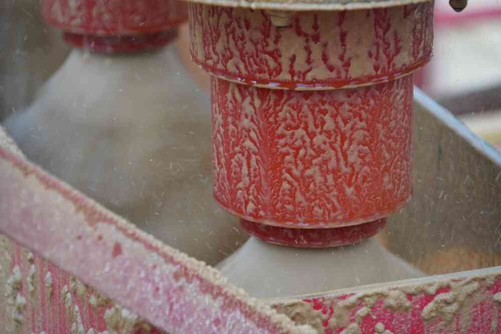
If the Hydrocyclone or Separator™ spigot is not discharging correctly, it could be caused by several factors:
- A blocked spigot – a blocked spigot can cause an increase in pressure and all material to report to the overflow. If the spigot is blocked, remove it and clean it out.
- A blocked inlet – a blocked inlet can cause an increase or decrease in pressure, depending where the blockage occurs in relation to the pressure gauge. It can also cause a reduced flow or no flow to the overflow and underflow. If the inlet is blocked, dismantle the inlet piping and clear it out.
- A loose liner – a loose or collapsed liner can have various effects. If the liner is loose or collapsed, remove or reseat the liner.
- Insufficient feed flow rate – insufficient feed flow rate can present as low feed pressure without a blockage and a spray effect out the underflow. If the feed flow rate is insufficient, check the Pump flow rate.
Challenge: high-density or roping underflow discharge
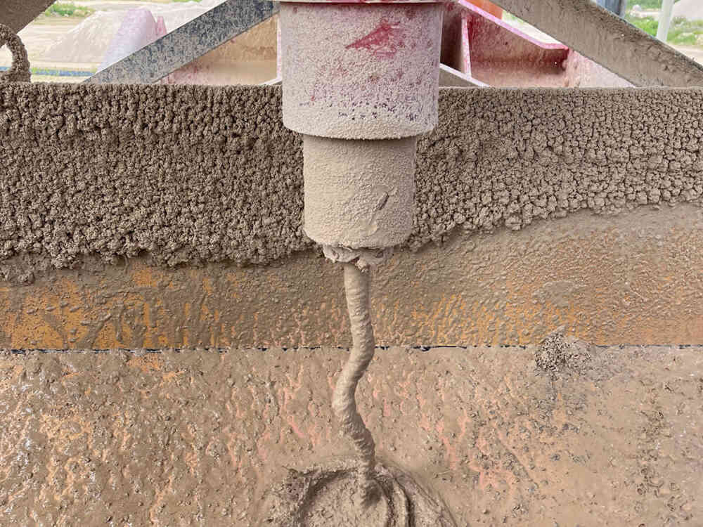
If the density of the underflow discharge is too high, or you notice the underflow resembles an old rope, it could be because the feed density is too high or the spigot is too small. If the feed density is too high, reduce the tons per hour of solids in the feed. If the spigot is too small, replace the spigot with a larger size.
Challenge: Separator™ underflow density not maintained – flushing
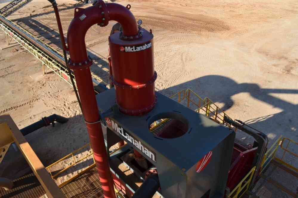
A flushing underflow could be caused by several reasons:
- The overflow pipe siphon control air bleed valve is too far open. If the valve is too far open, close the valve until it stops flushing.
- The overflow pipe length has been shortened, thereby eliminating the siphon effect. If the overflow pipe is too short, install the proper length of overflow pipe, which should be 6’ below the bottom of the Separator™.
- Insufficient feed volume of slurry to the Separator™ - check the feed supply to ensure the proper flow volume.
- A restriction blocking the overflow pipe - check the overflow pipe and remove the blockage as necessary.
- Slurry feed to sump is causing air bubbles to enter Pump suction. If this is the case, modify the sump entry by installing baffles or changing the location where the feed comes into the sump.
- A leak in the air hose between the siphon air control valve and the overflow pipe – repair or replace hose.
- A hole in the overflow pipe assembly that allows air to enter – repair the hole or replace the overflow pipe.
- A hole or other damage to the rubber underflow regulator on the bottom of the Separator™ - replace the underflow regulator.
- A section of rubber liner inside the Separator™ has come loose, blocking the performance of the Separator™. If this is the case, replace or reseat the liners are required.
Challenge: Separator™ underflow density varies with intermittent flushing
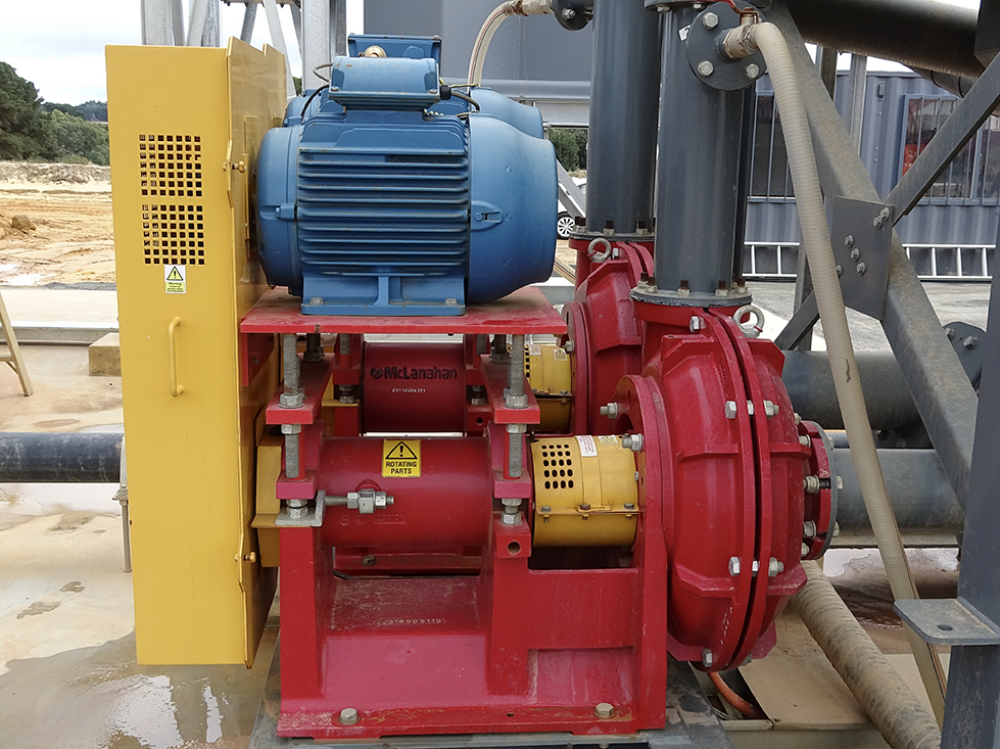
Varying underflow density with intermittent flushing can be caused by the following:
- The level of slurry in the feed sump is rising and falling. If this is the case, increase water to the sump or recirculate some of the overflow water back to the sump to maintain a more constant sump level.
- The solids are intermittently building up in the sump and slumping in the Pump suction. If this is the case, correct the sump design.
- The v-belts on the Pump are slipping. If the v-belts are slipping, tighten or replace worn belts.
- An obstruction in the Pump – shut off the pump and remove obstruction.
- The solids feed rate to the Separator™ exceeds design maximum (25% solids by weight) at times, thus starving the Separator™ of water. If this is the case, control feed solids to within maximum loading.
Overflow
The nature of the overflow makes this a harder area to monitor, as it is usually out of sight and in a difficult area to reach. Excessive material in the overflow stream can go unnoticed for weeks or even months.
During installation, a sampling point should be considered to help troubleshoot potential issues. Sampling the slurry helps to determine Hydrocyclone or Separator™ performance.
Like the underflow, the overflow can present an issue even if the source of the problem may be in the feed. With Separators™, it is extremely important that the overflow pipe fills up with water to create the siphon. Several reasons it may not fill with water include low water content in the slurry, low pressure, high pressure, a blockage (full or partial), air in the slurry and improper install/design.
Challenge: Overflow discharge is intermittent
If the overflow discharge is intermittent, it could be caused by one of the following:
- A collapsed vortex finder – if this is the case, replace the vortex finder.
- Insufficient feed (low feed pressure) – if this is the case, shut off the Hydrocyclone or Separator™ and add more feed volume.
- A blocked inlet – if this is the case, dismantle the inlet piping and clear it out.
- A loose liner – if the liner has collapsed or become loose, remove the liner and replace or reseat it.
- A blocked vortex finder – if this is the case, remove the vortex finder and clean it.
Challenge: Separator™ overflow water contains solids desired in underflow product
If the overflow water contains solids that are desired in the underflow product, it could be caused by several reasons:
- The siphon control air valve is too far closed, causing excessive siphon. If this is the case, open the air valve in small increments and sample the overflow until the desired result is achieved.
- The solids rate of feed to the Separator™ exceeds the specified design rate. If this is the case, reduce the solids concentration to design parameters (no more than 25% solids by weight.
The operating pressure may be too low to achieve the desired cut. If this is the case, verify the pressure and flow rate to the Hydrocyclone.

Overall
Troubleshooting a Hydrocyclone and Separator™ can be straightforward. Monitoring the inlet pressure is key for many operational issues, which are mostly issues with the feed system, such as the sump/Pump combination. Detection of a blockage comes from observing and sampling the overflow and underflow of the units. Occasional inspection of the internal components can prevent failure of the liners, spigot and vortex finder, while daily visual inspections can provide early indications of trouble.


